Resistors and Potentiometers:A Practical Guide
Second only to capacitors, resistors (and their variable cousins, the potentiometer) are the most commonpassive components found in stompbox designs. So here'san overview on types, what they do, and how to use them.
Note: This content is about the practical application of resistors andpotentiometers, as used in guitar and audio circuits. So I will avoid re-hashingall the basics of Ohms law, reading color codes, or other topics that are readilyavailable on the web. See the resources section at the end for links.
A resistor is a pretty simple beast: it is made up of a compound that resists the flow of current. It has twoleads and is not polarity-sensitive; in other words youdon't have to worry about the order of the leads.
First up, a brief list of things to know about resistors:
- Resistor values are quoted in Ohms.
- Resistors have various power ratings, signifying the power they can accept. For stompbox use (typically 9-18 volt DC supplies) 1/4 watt power rating is fine.
- If you like puzzles and memorization, you can learn and memorize the color-coding of resistor values. Or, if you are like me, you can cheat.
- The most commonly used resistor type in stompboxery is carbon film. You can use other types, but carbon film is cheap, reliable and easily obtained.
- If you lack a specific resistor value, you can use the formulas for Resistors in Parallel/Series to cobble together a specific value.
- Most resistors have a specified tolerance (for example 1% or 5%). So it is rare that a standard resistor will measure out to exactly its claimed value.
Resistor Types and Compounds
Resistors come in a wide variety of types and ratings. The most common guitar effect resistor type is carbon film, axial leads, 1/4 watt, 5-10% tolerance. You can use this type across pretty much every type of guitar effect/stompbox design you come across.
| Type | Typical Tolerance | Comments |
| Carbon Film | 5% | This is the most common type of resistor used in guitar and effect circuitry. Common, reliable and inexpensive. |
| Metal Film | 1% | A bit more expensive, but you get a closer tolerance. Additionally, metal film as a compound generally has lower noise and better temperature stability. |
| Carbon Composition | 5% | An older compound, found in vintage electronics. Sometimes employed by boutique builders for mojo or tone. |
Which Type of Resistor Should I Use?
In general, carbon film and metal film are absolutely fine for stompbox work. And resistors are the most inexpensive passive components you'll buy. So you can stock up on metal film parts for very little money.
There are some that say the older carbon composition resistors add mojo to a circuit. In my experience, this isn't really noticeable, unless you are building high-voltage tube circuits and want to remain faithful to original designs.
It's also worth thinking about specifications for tolerance and noise:
Guitar pedals are not high-fidelity devices. Indeed, the most common circuits are for overdrive, distortion, and fuzz which are all about distorting the input signal. And then think about your guitar pickups and their inherent noise, finally terminating in a noisy tube amp cranked up way to loud. With all these factors, is the noise rating of a resistor really going to change things? Probably not. Regardless, if you use metal film resistors, that resistor, in and of itself, is not going to add an appreciable amount of noise to your circuit.
So what about tolerance? Don't I need to use 1% parts to get as close as possible to an original design? Well, if you look at the inside of commercially built pedals, you'll find a plethora of 5% parts. The circuit was designed with these variances in mind. So your attempt to use 1% tolerance parts to match a design that was perfectly happy with 5% parts may not yield the results you are looking for. But as with noise, use metal film resistors if you want.
Cheating on the Codes
I'm useless at codes and puzzles and memorization. So I gave up long ago on trying to remember the resistor color code guide. What I found to be very easy is to buy a big batch of resistors, and organize them into envelopes with the value written on them. Makes part-picking and PCB populating much quicker.
And when in doubt, you can always pull out your multimeter and test the values. Remember that the tolerance of the part means you won't get an exact value, but it will get you close enough to know whether you are looking at a 10K part or a 12K part. Finally, a little tip: when measuring resistors, don't hold the leads with your fingers--that will add resistance that may cause an inaccurate reading. Instead, use test-clip leads, or lay the resistor on a non-conducing surface and measure it there.
All About Potentiometers
Potentiometers (or pots, as we'll call them) are incredibly versatile devices. They can act as voltagedividers, or as variable resistors. There are tons of resources on the web about pots, so what I'm going to cover here are the basic types, operation, and uses specifically for guitar audio.
Types of Pots
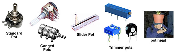
Pots come in all sorts of shapes and sizes. The most common type we use in pedals and amps are usually of the 24mm or 16mm round metal can type. There are also multi-gang pots (which stack multiple independent potson one shaft), slider pots, trimmer pots, etc.
In the case of a standard pot, as shown above, we have a round case with three connectors and a shaft that turns. Here's what it looks like in a schematic:

Lugs and Numbers
One of the first (and most common) mistakes in using potentiometers is misreading the frontversus the back and the lug numbers.
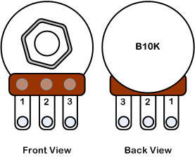
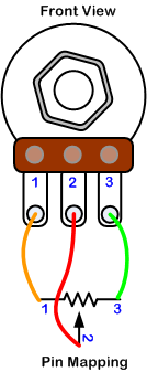
The pot has three lugs and by convention they are numbered 1,2, and 3. Pin 2 is called the wiper. These numbers map to the schematic symbol like this:
Tapers
Pots come in different tapers. The taper defines how the resistance of the pot changes inrelationship to turning the shaft.
- Linear Taper: The simplest form. The rotation of the knob directly corresponds to the resistance change in linear fashion.
- Audio/Logarithmic Taper: This taper compensates for how the human ear perceives changes in volume. It has a different curve--the resistance change as you turn the knob is not linear. Note that audio taper is the same thing as logarithmic (or 'log' as you will sometimes see it). Just different names.
- Reverse Audio/Log Taper :This has the same curve as the audio taper, but in reverse.
The following diagram shows the relation of resistance change as you turn the pot knob
Which leads us to the most common first question about pots: when do I use linear and when do Iuse audio? The answer is, do whatever the schematic or layout you are working from specifies.
Volume controls typically use an audio taper because it is designed to change the resistance on a curve that is smoothed out given how our brains interpret changes in volume. Linear tapers are usually used for other parts of the circuit such as tone controls, distortion levels, etc. But not always!
The good news is that you can interchange linear and audio tapers in a pinch. If a project calls for a 100k audio taper and you only have a100k linear taper, the linear one will work. In otherwords, the exact same changes in resistance will be available on audio/log and linear tapers, it just depends on where you have the knob turned to. In general, stick to the specified taper for best results.
Codes and Numbering
Of course it would be too easy if manufacturers would simply print the value and type of taper on a pot in plain English. But they don't, instead they use codes. Very simple to figure out though.
The code is:
- A single letter, A for audio/log, B for linear
and
- Numeric value, i.e. 10K
So a 100kΩ; linear taper would be B100K. A 1k audio taper would be A1K. There, now you know the code. It should be noted that back in the old days the A and B were reversed--if you are working some old mystery pots, the above coding scheme may need to be reversed.
Ok, Why Three Lugs?
The most confusing thing to me about pots was that it had three lugs. Why? I mean a resistor only has two connections, shouldn't a variable resistor also have just two connections? Well sure, and there are variable resistors (called rheostats) that only have two connections. But if you add a third lug, the humble rheostat becomes the mighty potentiometer.
As you turn the shaft, the resistance between the wiper and lugs 1 and 3 changes inversely. For example, if you turn the shaft clockwise, the resistance between 1 & 2 increases while the resistance between 2 and 3 decreases.
So if you think about it, the resistance between lugs 1 and 3 never changes. If you have a 100k pot, the resistance between 1 and 3 will always be 100k no matter how you turn the knob. It is the wiper (lug 2) that changes.
The Trimmer Resistor
Let's look at one of the most common uses of a potentiometer: as a trimmer resistor. Here's what the schematic looks like:
Here we have a potentiometer where lug three is the input, and lugs 1 and 2 are connected together to form the output. As you turn the shaft, the resistance decreases. You are forming a simple resistor whose value is variable.
'Wait a minute!' you might say. Why do I need to connect lug 1 to lug 2 if all I need is a variable resistor, like this:
Well that certainly works the same way. But what happens if the potentiometer fails for some reason (age, poor quality, dirty, etc.)? If the wiper (which is the rotating part of the component and probably most prone to failure) shorts out, it will let the full amount of signal through. By attaching lug 1 to lug 2, we are building in a fail-safe. This ensures that the circuit is never completely open--there will always be some resistive path in case the wiper goes south.
Ok, so where are trimmers useful?
The pots we've looked at so far are the typical panel-mount variety. They are mounted on the equipment's enclosure and usually attached to a knob so you can control the circuit. Trimmers are potentiometers that are typically directly mounted to the circuit board. They are a set-and-forget type of device. When a circuit is built, there is sometimes the need to tune it correctly. For example, if you have a stompbox that uses certain types of transistors, you'll want the transistors to be biased properly. This relies on resistance. So a trim pot would allow you to dial in the correct voltage, close up your stompbox and be on your merry way.
On a philosophical note, I'm generally opposed to using trimmers where a panel-mount pot would offer some control over the tone. For example, some modulation pedals have trimmers to control the range of an affect. These are often fine-tuned by the manufacturer with trim pots. However, by burying that control inside the box, you may be missing out on some interesting tones. Of course, there are places where trim pots make sense--i.e. when they are used to tune a circuit and any variance beyond the factory tuning and anything else is not musically useful.
What About those Pesky Tabs?
Most pots come with a small metal tab that sticks up in the same direction as the pot. These are used for anchoring the pot firmly in the enclosure. If you are so inclined, you can drill an additional small hole in your enclosure to use this tab. If you are like most of us DIY folks, you'll just snap the tab off before mounting the pot.
Fun with Pots
Ok, let's have some fun with pots. First off, we'll build a voltage sag circuit. This allows youto simulate a dying battery which can yield some interesting tones in certain types of circuits,especially fuzz effects. Here's the general way a battery is connected to a circuit board:
To sag the voltage, we'll introduce a pot between the battery positive connection and the circuit board, like this:
Now, as we turn the potentiometer, we increase the resistance between the battery and the circuit, thereby lowering both the current and voltage.
A Volume Control
Now let's look at another example: a volume control. Assume we have a simple stompbox that does distortion or overdrive or something else interesting. At the end of the circuit we have an output. Wouldn't it be nice to control the output level or volume) of the pedal?
Here we have the signal going to lug 3, the output coming out of lug 2, and lug 1 connected to ground. To see how this works, assume you have the shaft turned all the way clockwise, i.e. turned all the way up. In this configuration,there is little if any resistance across lugs 2 and 3 so the maximum output signal goes to the output.
As you turn the shaft counter-clockwise, the resistance across lugs 2 and 3 increases and the resistance across lug 1 and 2 decreases. This causes more of the signal to be dumped to ground. This dumping essentially sends the signal into oblivion, thereby lowering the overalloutput level.
So if you think about it, you are never really turning the volume up! The volume or level in the circuit is always running at full tilt. What you are doing the above volume control is actually attenuating (making smaller) the full volume that was there to begin with.
A Passive Mixer
Generally you want any mixing circuits to be active (i.e. to include opamp or transistor components to match and balance the inputs). However, you can squeak by in some cases with a passive mixer. Although the passive design can load down the input devices, it will work fine in many cases.
Here we are going to use an audio taper pot for each input channel:
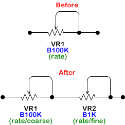
A Fine Pot
You may have seen pedals with a speed or time knob. Typically speed is for LFO (low frequency oscillator) such as in a phaser or chorus. And time knobs are in time-based effects such as delays. And sometimes, you may have seen an arrangement of two knobs for speed or time; one to control the coarse value and one for fine value.
In other words, the coarse pot makes big changes in values, the fine pot makes small changes. The fun part here is that it is super easy to implement such a scheme: just use two pots instead of one. In the following example, we augment an existing 100K pot with a new 1k pot:
Make a Tone Control
You can also use a pot and a handful of components to build a simple tone control that you can retrofit into any pedal that lacks one. Look at the following drawing:
The input accepts the signal. It passes through a R1 and C1 which form a filter network. R2 and C2 form the other side of the network. (Note the different component values). As you move the pot shaft, more signal is sent to one side or the other of the tone network. The wiper of the pot (lug 2) is the output. This is a simplified explanation of the tone control, but it shows how the wiper allows you shift the signal from one side of a circuit to another.
Wrapping Up
Pots are everywhere. Because they are so useful I guess. Here are some additional resources on the web for further research:
The Secret Life of Pots: http://www.geofex.com/Article_Folders/potsecrets/potscret.htm
Beginner's Guide to Pots: http://sound.westhost.com/pots.htm

This work is licensed under a Creative Commons Attribution-NonCommercial-ShareAlike 4.0 International License.