Optochopto: Fun with the Colorsound Inductorless Wah
The old Colorsound Inductor-less wah circuit is a fun and easy project. You don't need an inductor and it lends itself to all sorts of fun variations. First let's look at the stock schematic.
Colorsound Wah - Stock Schematic
What we have here is a simple single-transistor amplifier connected as a twin-t filter. The pot at the bottom provides the "wah" function. So the first thing you can do is simply build the circuit with the VR1 control as a pot with a knob on it and you have a cocked-wah pedal: set any wah position manual and you're good to go.
Add a Low Frequency Oscillator
But what if you replace the VR1 pot with a low frequency oscillator (LFO)? Now you have a tremolo that uses the wah position to set the volume up and down. This is an interesting take on the usual tremolo function which typically just shunts the signal to ground or changes the amplification factor up and down using an LFO. So how do we go about replacing a pot with an LFO?
Well first, we need an LFO circuit to generate the up/down voltages and to provide control for speed. For my experiment I used a simple Schmitt trigger. Here's how it looks:
Simple LFO
Pretty simple: I use just one gate of a 40106 Quad Schmitt Trigger. The combination of C1 and VR1 set the range of speed. R1 is a limiter resistor so the LFO doesn't get to fast. At the output there is a simple on/off voltage pulse in the form of (roughly) a square wave.
So know we have a voltage pulse whose time we control. The next question is how to convert a voltage into resistance. After all, we are trying to replace the VR1 wah pot which is a variable resistor. The answer is in the form of a Vactrol--a device that uses an LED and a photo resistor encapsulated in a way the keeps outside light out. After much experience, I settled on the VTL5C9 as it provide a good balance between time and resistance. I also added another pot, VR2, so I could control the intensity of the signal sent to the vactrol.
Simple LFO with a Vactrol
Now lets' put it all together.
optochopto - complete schematic
Here you can see the LFO hooked up to the vactrol, then to where the VR1 pot was on the original schematic. For fun I added three different capacitors on a Peak switch and then on to a 100K linear pot to add a bit more control.
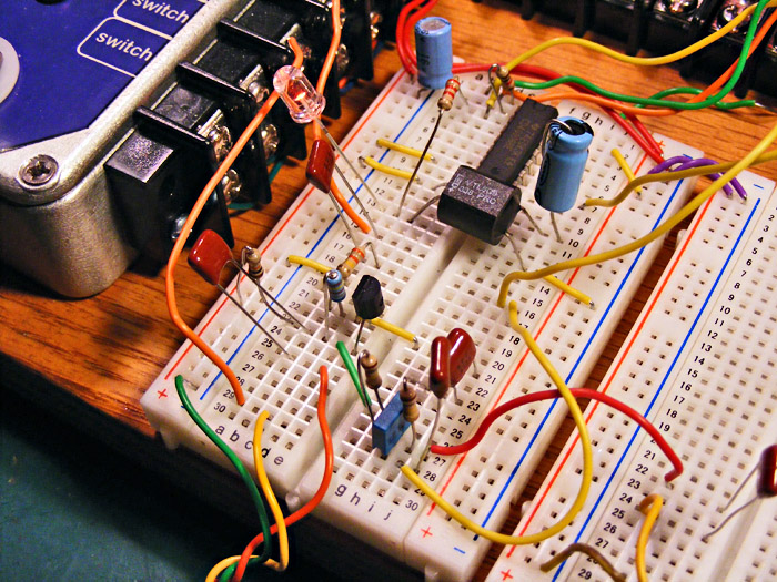
optochopto - on the breadboard
Plus, a Free Bonus!
While I was breadboarding this, I wondered what just the boost part of the circuit sounded like. I disconnected all the wah and LFO goo and lo and behold, it is actually a very nice sounding boost. Adds a bit of sparkle to your tone. Give it a try!
Booster extracted
