Digital Sequenced Wah Filter!
or A Damn Long Article on a Better LFO
Low Frequency Oscillators are pretty common in stompboxes, and are used to modulate everything from chorus to delay to tremolo pedals. There are a wide array of LFO designs out there based on traditional op-amp or transistor designs, but they are very limiting. By limiting, I mean that you implement them and get a very traditional LFO, it ramps up and down. Of course you have depth and speed controls to vary the LFO, but it is still a purely up/down affair. If you want to get fancy and add sequencing or other more interesting waveforms, you need to design, debug and build circuits with a lot more components.
Don't get me wrong--there are a lot of fantastic LFO circuits out there, but I found myself looking for somethingdifferent. As I pondered the design for a truly flexible LFO/sequencer, I remembered the work I did on the Arduino Punk Console, a microcontroller based tone sequencer. I really enjoyed that project because it allowed me to use my programming skills (which far surpass my often bumbling electronic skills). I could write code, test it, tweak it, modify it, all with the computer.
That experience led to a different approach for an LFO design: one controlled by a microcontroller.
Here's what I wanted to accomplish:
- Standard adjustable LFO, with speed and depth controls
- Sine wave and Square wave output
- Random values output
- Sequencer control, i.e. select specific values for multiple steps and have it playback
- Real-time user control over various parameters
- Experimentation with composites and bastardizations of the above.
The Big Picture
The microcontroller (MCU) is responsible for sending variable voltages over time (just like a traditional LFO) to an effect that can be modulated by a voltage, or a pot on a traditional analog effect that can be replaced with an optoisolator/vactrol. Here's a block diagram:
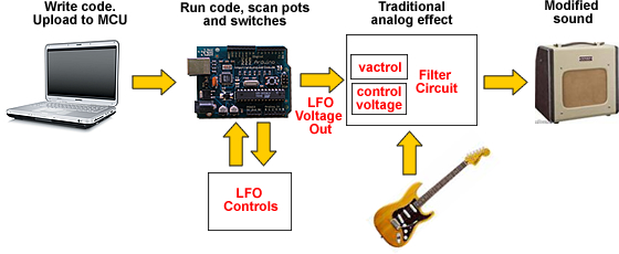
- On the left, we write some code that tells the MCU to output voltages based on program variables. We also have the MCU read various pots and switches connected to it. This gives us real-time control over the parameters of our LFO program.
- Once the program is ready, we upload it to the MCU. If it compiles and executes properly, we are ready to move on to the next step. If not, we go back to the computer and debug the problem.
- The MCU then sends a series of voltages to the input of the analog effect. We can do this directly with a Control Voltage, or have the MCU drive an optoisolator/vactrol to act as a potentiometer.
- From there, the guitar plugs into the effect and then an amp and we are ready to hear the results.
An Important Note: If you are new to MCUs, you may get the impression that a laptop or desktop computer always has to be part of the equation. In other words, you couldn't make a real effect pedal because you'd always have to cart around your laptop.
Not true! The computer is where you write, test, and fine-tune your code. Once you have downloaded the code to the MCU, you can disconnect the laptop, stick the MCU in an enclosure along with the traditional jacks and switches, and never have to reconnect the computer. Even if the MCU loses power, it will retain its programming. So having MCUs as part of a stompbox/pedal design is very feasible.
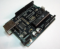
Enter the Arduino, Stage Left
Since I already had a basic knowledge of programming the Arduino microcontroller, choosing that for the LFO engine was simple. I have a few Arduino boards in the parts bin, so away we go. Here are some of the basic things about the Arduino that make it a very nice fit with this project:
- Fairly low cost: You can get a complete development board for under 40 dollars.
- Easy to program: The Ardunio includes a very simple software development editor and a simplified Java-like language
- Open Source: Unlike closed proprietary systems, the Arduino is open-source. You aren't locked into a single vendor or technology. There are tons of industry standard parts you can interface with, and at least four different sources for Arduino or Arduino-compatible boards.
- Lots of Ins and Outs: analog in/out ports, and digital in/out ports, already on the board.
Of course, you can use any MCU, and there are hundreds of variations to choose from. Google the topic and you'll find a lifetime of learning and fun ahead.
MCU Interfacing with the Physical World
Remember the design goal of "Real-time user control over various parameters"? Well in a traditional computer application, you'd have a screen and a keyboard and a mouse, and interact with the program and computer through things like menus and scrollbars, and the like. But we want a hardware-based interface. So we want to set parameters with the things we like to see on stompboxes: pots and switches.
Fortunately, MCUs make this incredibly simple. Our MCU has a set of analog-to-digital converters (ADCs). They sample an analog voltage and turn it into a digital value that our program can then read.
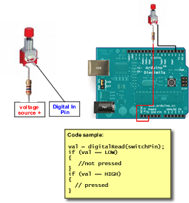
Reading a Switch
The most basic example is a switch:
Here is a great tutorial on working with Switches on the Arduino.
Reading a Potentiometer
Pots are easy too. You simply wire the pot up as a voltage divider and have its output go to one of the ADCs on the MCU. As you turn the pot, you vary the voltage going into the ADC, and your program simply reads that value:
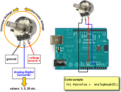
To implement a voltage divider with Arduino, connect lug 1 to ground, lug two to one of the analog inputs, and lug 3 to the 5 VDC+ pin. Then use a single simple line of code to read the current value, as shown in the Code sample.
The combination of devices is endless. You could replace pots with light-dependent resistors, or a joystick,or an ultrasonic range-finder. Similarly, switches could be replaced with other controllers, or even interfaces to other MCUs or computers. That's one of the beauties of using an MCU--there are lots of easy ways to interface with the physical world.
All About PWM
In order to create a workable LFO, one of the key requirements is: I need to have the MCU send out a continuously variable voltage that varies over time. But the MCU is traditionally a binary/digital device. It doesn't natively support a continuously variable analog range, like voltage. So I'm sunk right?
Not sunk at all: PWM to the rescue.
The Arduino, along with most MCUs, allows you to output a variable voltage. It accomplishes this through the use of Pulse Width Modulation. I would be crazy to try to explain PWM in detail here given the number of excellent articles on the web, but suffice to say, the MCU uses a series of very tightly spaced on/off pulses to simulate an analog output. I use the analogWrite() function to output a value from 0 to 255. A value of 0 means 0 volts at the LFO output, and 255 means an output of the full supply voltage (5 volts in the case of the Arduino) to the LFO output.
Here's a great graphic, pilfered from wikipedia, that shows how a PWM output can simulate an analog waveform:
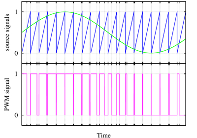
The interesting thing about PWM is that it does not output smooth linear analog type curves. It is on/off at specific intervals. But we can get smoothed curves out of PWM by stepping through values in a loop:
                                // Hard on/off output

                                  analogWrite (outPin, 255); // Hard on

                                  delay (100);

                                  analogWrite (outPin, 0);   // Hard off

                                  delay (100)  // A smoother approach

                                  for (counter=0; counter<=255, counter+=1) // ramp up

                                  {

                                    analogWrite (outPin, counter);

                                  }

                                  for (counter=255; counter<=0; counter-=1) // ramp down

                                  {

                                    analogWrite (outPin, counter);

                                  }
The first snippet bangs the output on, pauses, and then bangs the output off. The second is a bit more subtle, it gradually ramps the voltage up from 0 to 255, and then gradually ramps it back down. Both of these types of output modulation are useful, and I'll use both in the code for my LFO.
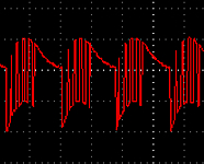
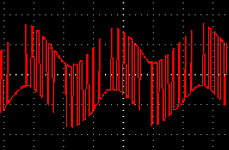
To get a better idea of how PWM tries to approximate linear/analog-y curves, see the waveforms shown in the Modes table below.
Let's Talk in Code
The heart of making this crazy scheme work is programming: writing code to tell the MCU what to do. We want the MCU to:
- Initialize correctly when it is powered up
- Continuously scan the controls connected to it (pots and switches)
- Modify its behavior based on the controls
- Output voltages to the effects pedal.
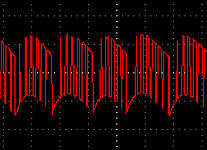
To create the most flexible LFO, I decided to create different LFO modes. Each would use a different algorithm to modulate the LFO in a different way. Here's what I came up with. Each mode is explained along with a code snippet and a picture of the waveform.
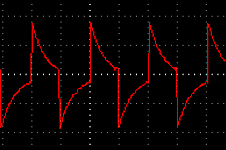
Chopper Mode
The Chopper mode is a hard on/off output waveform. I simply turn the LFO full on, wait for the amount of time specified by the rate potentiometer, turn the LFO full off, wait again, and then repeat. The simplified code looks like this:
                            digitalWrite (PIN_PWMOUT,
                            HIGH);

                            delay (tempo);

                            digitalWrite (PIN_PWMOUT,
                            LOW);

                            delay (tempo);
Soft Chop
By modifying the Chopper algorithm, I can make the chop a bit softer. I do this by adding ramp up/ramp down values to soften the output a bit.
                            analogWrite (PIN_PWMOUT,
                                        25);

                                        delay (tempo/9);

                                        analogWrite (PIN_PWMOUT, 50);

                                        delay (tempo/9);

                                        analogWrite (PIN_PWMOUT, 75);

                                        delay (tempo/9);

                                        analogWrite (PIN_PWMOUT, 100);

                                        delay (tempo/9);

                                        analogWrite (PIN_PWMOUT, 150);

                                        delay (tempo/9);

                                        analogWrite (PIN_PWMOUT, 180);

                                        delay (tempo/9);

                                        analogWrite (PIN_PWMOUT, 255);

                                        delay (tempo/2);
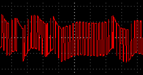
Stairstep
This mode walks through a loop, incrementing the output LFO voltage by a chunk at a time, leading to a stair-step type of LFO wave.
                            for (counter = 0; counter <= 255; counter += 25)

                            {

                              analogWrite (PIN_PWMOUT, counter);

                              delay (tempo/10);

                            }

                            for (counter = 255; counter >=0; counter -= 25)

                            {

                              analogWrite (PIN_PWMOUT, counter);

                              delay (tempo/10);

                            }
Wave
The Wave mode simulates a sine wave by ramping up and down through the output voltage with a smaller chunk interval.
                            for(counter = 0 ; counter <= 255; counter+=25)

                            {

                              analogWrite(PIN_PWMOUT, counter);

                              delay (tempo/10);

                            }

                            for (counter = 255; counter >= 0; counter-=25)

                            {

                              analogWrite (PIN_PWMOUT, counter);

                              delay (tempo/10);
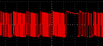
Random
Random mode uses the Arduino Random() function to generate a random number. Note that I try to normalize these values a bit, I don't want a lot of "full-off/zero" values in there. Remember to get the Random function to do a reasonable job of, well, randomness, you need to call the Randomize() function at the beginning of your code. In my case, I set the seed value of the input voltage of an unused analog input--the theory being that there is going to be some kind of noise on that unused port, and it would make as good a seed as any.
                            // random mode, get a random number between thresholds

                            int randNumber = random(RAND_LOW_THRESHOLD, RAND_HIGH_THRESHOLD);

                            analogWrite (PIN_PWMOUT, randNumber);

                            delay (tempo/2);

                            analogWrite (PIN_PWMOUT, 255 - randNumber);

                            delay (tempo/2);
Frequency
This mode is a variation on the Random mode, and actually sounds a lot more pleasant if you are looking for a 'sample and hold' type of sequence. Like the Random mode, it generates random numbers, but instead of just sending that random number as an output voltage value, it sends it to Paul Badger's very cool FrequOut() function which uses PWM to generate audio frequencies on the output port.
                            int randNumber = random(tweak,tweak*4);

                            freqout (randNumber, tempo);

                            CheckControls();
Tunable
Tunable is fun: like Frequency Mode, it uses the FreqOut() function, but instead of random voltages, it uses a pot to control the actual frequency.
                            int fixed = analogRead (PIN_MODETWEAK);

                            freqout (fixed, tempo/2);

                            freqout (1024-fixed, tempo/2);
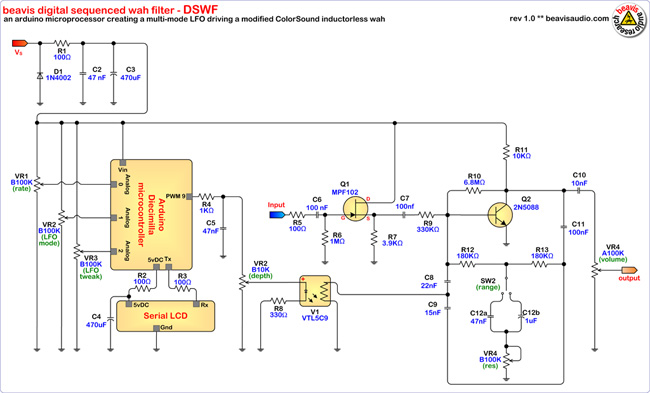
The Filter/Wah Effect
Of course, an LFO on its own is pretty useless unless it is actually controlling something. As mentioned earlier, you can use this LFO to control all sorts of things. For my purposes with the Digital Sequenced Wah Filter, I wanted a circuit that would behave nicely as a wah and as a pseudo tremolo. Turns out that the Colorsound Inductor-less Wah design, with a few tweaks, works quite nicely. My modifications to the circuit include:
- the addition of a JFET buffer in the front of the circuit (Q1, etc.)
- larger coupling capacitors (C2 and C3)
- A switchable range for the resonance capacitors (SW2, C6a, C6b)
- A tunable resonance with the addition of a pot (VR4)
- Replace the wah pot with a VTL5C9 vactrol
An Important Note:
The schematics and PCB art are preliminary and unverified at this time.
Bringing it all Together: Interfacing MCU to Effect
The two general ways to interface the LFO to a circuit are to directly use the LFO output voltage (ala Conntrol Voltage), or to use an optoisolator to replace an existing potentiometer in the circuit. Since I'm using a circuit that already has a pot to control the wah, the choice of an optoisolater is easy. I went through a variety of commerical optoisolators, using PerkinElmer VACTROL devices. The one I settled on is the VTL59C. It had the fastest response time and best overall curve for my specific circuit.
In order to tame some of the noise coming off the MCU before it hits the vactrol, I put in a simple filter consisting of R4 and C5. The Vactrol also had an unanticipated side effect--its latency helped smooth out the rough steps/peaks from the PWM output.
For Display Purposes Only
Since I have controls for rate, mode, and mode tweak, it sure would be nice to have the pedal display what's what. I could use traditional LED indicators, but that would serious underkill since I have a MCU that supports a serial output port at my disposal.
All I need now is a display device that has a serial input. Sparkfun Electronics takes care of that part for me. They offer a variety of LCD panels, but the cool thing is that they add a small serial
input board, called the SerLCD. This add-on board eliminates the tedious work to get a parallel interface LCD display to work. Instead of all the misery, I simply connect three wires from the LCD to the Arduino and write a little code.
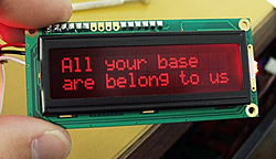 Great LCDs from SparkFun
To connect the LCD, I run wires to 5vDC+, ground, and serial TX:

The code for accessing the LCD is a bit tricky, mostly because the documentation is designed for generic MCU use, not specifically for the Arduino. There is also another issue that made me pull my hair out for days: the serial in/out on the Arduino is shared with the USB port. So when you upload your program from the computer to the Arduino, the object code gets dumped the serial port also. This means that all that random binary data is getting dumped into the LCD as gets loaded in to the microprocessor. This can leave your LCD in a confused, and often dead, state.
To get around this problem, you have two choices. 1) Always remember to disconnect the SerLCD board's RX wire from the Arduino TX port BEFORE uploading a program. This is easy, but I guarantee you will forget to do it every time, and that means you will farkle up the LCD board, just like I did one thousand times. A better approach involves re-initializing the LCD every time your Ardunio starts up. Here is the start-up code I use:
                            //*******************************************

                            // LCD STUFF

                            // beavis audio/march 2008


                            // LCD control constants

                            #define SERLCD_CMD 0xFE

                            #define SERLCD_XCMD 0x7C // Dec
                            124

                            #define SERLCD_CTRLK 0x0B

                            #define SERLCD_CTRLM 0x0D

                            #define SERLCD_CTRLJ 0x0A

                            #define SERLCD_CLEAR 0�01

                            #define SERLCD_MOVE1_R 0�14

                            #define SERLCD_MOVE1_L 0�10

                            #define SERLCD_SCROLL_R 0�1C

                            #define SERLCD_SCROLL_L 0�18

                            #define SERLCD_DISP_ON 0�0C

                            #define SERLCD_DISP_OFF 0�08

                            #define
                            SERLCD_UNDERLINE_CURSOR_ON 0�0E

                            #define
                            SERLCD_UNDERLINE_CURSOR_OFF 0�0C

                            #define
                            SERLCD_BLINKING_CURSOR_ON 0�0D

                            #define
                            SERLCD_BLINKING_CURSOR_OFF 0�0C

                            #define SERLCD_SET_CURSOR_POS
                            0�80

                            #define SERLCD_CURSOR_OFF 0�0C


                            void LCD_Clear()

                            {

                              Serial.print(254, BYTE);

                              Serial.print(1, BYTE);

                            }


                            /* LCD_SetBacklight - set the
                            brightness of the backlight

                               int Bright - 128=lowest, 157=brightest */

                            void LCD_SetBacklight (int
                            bright)

                            {

                              // LCD expects values between 128 and 157

                              int value = bright + 127;


                              Serial.print (SERLCD_XCMD, BYTE);

                              Serial.print (value, BYTE);

                            }


                            void LCD_Init()

                            {

                              Serial.begin (9600);

                              Serial.print (SERLCD_XCMD, BYTE);

                              Serial.print (SERLCD_CTRLM, BYTE);

                              delay (300);


                              LCD_Clear();


                              // Set up the boot up message, this only needs to be

                              // flashed once


                              /* Serial.print ("beavis Digital");

                              Serial.print (254, BYTE);

                              Serial.print (192, BYTE);

                              Serial.print ("DSWF 1.0");

                              Serial.print (SERLCD_XCMD, BYTE);

                              Serial.print (SERLCD_CTRLJ, BYTE);

                              */


                              LCD_SetBacklight (30);

                            }


                            void LCD_Newline()

                            {

                              Serial.print (254, BYTE);

                              Serial.print (192, BYTE);

                                                }
Note that even with this start-up code, you may need to actually cycle the power on your Arduino board (disconnect the power to the board, wait ten seconds, reconnect the power) to get the LCD to work correctly.
Dealing with Noise
As I was developing this circuit, it was quiet as a mouse. No LFO bleed-thru, no hum or other unpleasantness. But that was because the MCU and the Wah filter were each on their own power supply. The MCU ran of the power supplied by the USB cable connected to the computer and the Wah was powered by the powered breadboard. Everyone was happy. As I started working towards finishing things up, one task was to run the whole shebang off a single power supply. After hooking this up, I was appalled: it was incredibly noisy: several different frequencies of hum, and a hugely audible PWM signal bleeding through. After some consultations with the oracles at DIYStompboxes.com, I add a lot of filtering on the power supply. In the schematic, you'll see 100 ohm resistors sprinkled throughout, along with a big 470uf cap. These all contributed greatly to getting the noise and bleed-thru down to manageable levels. It is still not dead silent, but I believe once I get this all onto a PCB and in a grounded enclosure, it will do nicely.
Ok, Enough Blather. Let's Build the Damn Thing
So I had this built and spread across an entire desk: laptop, USB interface cord, MCU, breadboard for MCU, power supply, wires to main breadboard, main breadboard, output jacks, etc. It was fun, but wouldn't actually fit on my pedalboard.

So how to make it into a pedal? One word: planning. I did the mockups in Visio, and the measured each component, figured out how it would fit in a box, and then built some paper templates to test it all out. The end result is a Hammond 1790NS enclosure to hold it all. Here's the layout so far.
PCB for the analog side of the house is done and ready for testing.
Still Lots Left to Do
As of this writing, there are still lots of things to do. Need to etch a PCB for the filter wah, drill the enclosure, and build it all up. Of course, the obligatory video/clips will have to happen to. In the meantime, I hope the coverage here is at least mildly interesting.
Conclusion and Areas for Further Study
The stuff discussed here only scratches the surface. Between the ability of a MCU to generate a seemingly endless array of output options, and the number of analog and digital effects that could be modulated by it, well there appears to be fertile ground here for experimentation.
If you want to learn more about some of the topics and technologies presented here, check out the following:
| Arduino Official Site: Learn more about the Arduino hardware and software | 8Go there |
| Bare Bones Board, a great low-cost Arduino clone | 8Go there |
| Sparkfun: nice online store for tons of MCUs, peripherals and displays | 8Go there |
| LadyAda: more great Arduino projects | 8Go there |
| Arduino Coverage on the Make Blog | 8Go there |
| Vactrol info from PerkinElmer | 8Go there |
| Another potential source for serial LCDs | 8Go there |
| Micro-controller DIY forum on electro-music.com | 8Go there |
