The Screamer Lab
The world's most modded TubeScreamer?
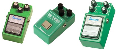
If you play electric guitar, there's a good chance that you own, have owned, have played, or at least have heard of the Ibanez Tube Screamer. The TS series has been around for many years, has been through many variations and remains one of the most recognizable overdrive pedals of all time. So it's not a surprise the that TS is also one of the most copied, and modified pedals out there. Indeed,an entire cottage industry of DIY folks, mod companies and boutique pedal makers has grown up around the Tube Screamer.
As I've been learning about effects circuits and building pedals, I've learned many things about the Tube Screamer and about all the different modifications that you can make. I've learned how to spot a TS clone in a second. And read a lot about what people like and dislike about the Tube Screamer. I've also learned that different people like different sounds--a mod or circuit that sounds great to me may sound like complete crap to you. And that's why mods are so great--they allow you to tailor a circuit to make a sound that is as close as possible to the sound you have in your head. To make a long story short, one size does not fit all.
In a previous project called the FuzzLab, I decided too apply this canned-is-bad philosophy to a fuzz pedal. One pedal built one way was not going to cut it--I wanted mods and different circuits, but I wanted to be able to change the mods on the fly without de-soldering and re-soldering components. This is certainly not a new approach. Many boutique vendors pick a few mods for a given pedal and make them switchable. But I want to go all out and take it to the next level. I want to build pedals that have as much user-controlled variability as possible.
So...when I decided to build a Tube Screamer pedal, it was time to spend many hours late into the night researching how the circuit works, the different versions in the TS family, and all the mods that the pedal community has dreamed up over the years. The result is the ScreamerLab--an Ibanez TS-808 Tube Screamer clone that has as many mods as practical available. This article describes the design of each mod, and also shows you how to go through, step-by-step and do it yourself. The resulting pedal is killer.
Standing on the Shoulders of Giants
As a relative newcomer to the art and science of building guitar pedals, I am faced with a huge array of questions that need to be answered before I design and build something. But I'm lucky. I have access to the greatest pool of talent in the world, all accessible through the web. My design for the ScreamerLab is based on the hard work of a lot of other people. Indeed the mods that I have designed are not Dano innovations at all--they are somewhat interesting variations built on the body of knowledge created by legendary and seriously smart people.
As such, the ScreamerLab is actually the product of the research, writing and thought by many people, most importantly:
- R.G. Keen
- BYOC Keith
- Jack Orman
- Robert Keeley
- AnalogMan
- The entire community at DIYStompboxes
- The crazy circus that is HCEF
Thanks folks, you give of your time to build and empower a growing legion of new pedal hackers.
Design Goals
Any project of even modest complexity needs clearly stated design goals. What are you trying to accomp are the bits and pieces and why are you doing them. In almost all engineering disciplines, including pedal building/hacking, Design Goals are the key starting point: what are your goals and how will your design accomplish them.
To provide an Ibanez Tube Screamer based pedal with the ability for the user to switch various parts of the circuits to enable and disable various modifications. The rationale for this is that there are many many Tube Screamer clones and modified versions on the market. But each vendor chooses their version of the tone and mods that are the end result. My idea is that, like the Beavis Audio Research FuzzLab, the user should have maximum control over the tonality of the effect.
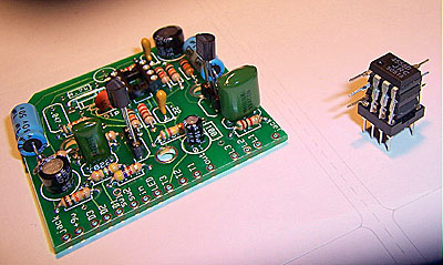
BYOC: The Starting Point
Several of my previous projects have been based on the great effects kits from Keith at BYOC. I had ordered one of his Screamer models which is pretty much a straight up clone of the TS808. As I worked out all the parts needed for this project, and contemplated the different PCB options, it became pretty clear that I would not save much money at all by building the project entirely from scratch as opposed to starting with the BYOC kit. Plus the BYOC boards are pretty much the best in the business--easy call.
The Wiring Diagram
Note: There have been several changes and corrections to the wiring diagram as I've been working on this project. Currently I'm on Revision C. If you have earlier versions, be sure to grab the latest--there are some mistakes in earlier versions.
Go to the wiring diagram.
Op-Amp Configurations
The opamp is a key component in the Tube Screamer circuit. Some users claim to be able to discern an audible difference in tone depending on the opamp used. Others claim it is snake oil and makes little if any difference. In the middle camp are those who say that opamp changes can provide subtle changes in tone coloration. In order to accommodate all camps, the opamp configuration of the ScreamerLab.
R.G. Keen (www.geofx.com) is generally one the most knowledgeable pedal guys of all time. His elaborate analysis of the tube screamer says that any of the following opamps would sound good in the Tube Screamer circuit:
- JRC4558D (comes with BYOC kit)
- LM833
- RC4558 (comes with BYOC kit)
- TLC2202
- TLC2272
- OP275
- LT1214
Robert Keeley of Robert Keeley Electronics (http://www.robertkeeley.com/) has been working with modding Tube Screamers and other pedals since the beginning of time. He states:
"Keeley Effects use the TI RC4558P like the old TS808 and they all come with a BLUE LED. * I have the TI RC4558P integrated circuit for your Ibanez Ts-9. This is what came in some early TS808 pedals. This will give your pedal TRUE TS808 sound. Many collectors agree that the TS808 with the TI4558P chip are some of the finest sounding pedals in the production."
Switching and Stacking
Most boutique builds of the Tube Screamer include a DIP socket that allows the user to change the opamp by physically removing the one in circuit an replacing it with another. This approach is certainly the simplest and cheapest route, but it has two key disadvantages:
- Changing the opamp can damage the opamp, the circuit
board, or both. In other words, it is not practical
except for those with at least a minimum of DIY
experience.
- By the time you have powered down the unit, unscrewed the case, swapped the opamps, reassembled the case, and powered back up, there is a good chance that you don't remember what the first opamp sounded like. Hardly a very useful proposition especially when want to do A/B testing.
So using s single DIP socket is not the way to go. Another approach is switchable opamp where a mechanical of CMOS switch is used to change between different opamps while the circuit is powered up. There are various approaches to this, from complex to fairly simple. The most complex would use CMOS switching and switch all eight of the pins. Indeed, one enterprising modder has come up with a way to switch opamps in a TS in one of his modded pedals. Check out www.mohomods.com for that solution.
For the ScreamerLab, I want to take a simpler and more interesting approach, called opamp stacking.
Stacking the opamps means that the opamps are physically soldered to each other, pin for pin, so you form a physical stack of opamps. In the circuit, the opamps are running in parallel. This has been considered before within the DIY community and offers a different take on opamp modification.
Stacked op-amps
Jack Orman (www.muzique.com), another highly respected and knowledgeable source about such matter, has the following to say about stacking:
"what you get is increased current drive. Typically, a small value resistor, 10-50 ohms is inserted in the output of each opamp before they are combined to the signal output. This ensures that the opamps share the drive more equally. Using a pair of opamps in parallel will actually decrease the noise by about 3db due to random cancellations. Four opamps in parallel would reduce it even further, but that's about the practical limit."
So stacking sounds like an interesting approach to use in the ScreamerLab project. But it has one drawback--basically you are getting a composite of the tone of each opamp summed together. I.e. you are not getting the ability to switch between opamps. So how do we get the benefits of stacking and the benefits of switching? This piece of the puzzle was provided by Keith of BuildYourOwnClone.com in one his forum posts:
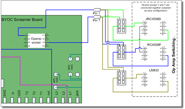
"Pin 1 and pin 7 are the outputs of each op amp. Wire both so they share all the other connections, but use a switch to connect or disconnect these 2 sets of pins. It could be done with just a DPDT."
Bingo! Now we have the ability to do both stacking and switching. In essence, the ScreamerLab will have three opamps stacked, but pins 1 and 7 of each opamp will remain open. We will then use a 4PDT switch to change between the inputs and outputs. The fourth position of the switch will connect pins 1 and 7 into the overall opamp stack.
Opamp Design
The ScreamerLab includes three opamps: the JRC4558D, the RC4558P, and the LM833 in a stacked, switched configuration. The JRC part was chosen because it is the most common stock Tube Screamer chip, the RC4558P because it is widely used in the boutique world, and the LM833 because it is a more modern, low-noise part. The low-noise characteristic is important when used in conjunction with the Distortion Boost Mod (discussed later in this document). The DBM introduces noise, so the LM833 can be used to mitigate the increased noise.
The opamps are physically soldered together in parallel with the in and out pins leading to switches. Each is constantly part of the circuit, and the set of DPDT switches adds or removes an individual opamp to or from the stack.
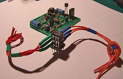
Stacked opamps with leads connected
TS-808/9 Mode
The difference between the original TS-808 Tube Screamer and the TS-9 is a couple of resistors. Again, from R.G. Keen:
"... just locate the 470 ohm and 100k resistors on the output buffer transistor, tracing back from the output jack, and replace them with a 100 ohm and a 10K. Bang, instant 808."
This is a pretty simple change. Instead of wiring the two resistors to the board, you wire both values to DPDT switches.
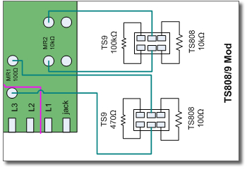
If you look at the wiring diagram, you'll notice that each resistor value is wired to its own switch. So in order to change from TS808 mode to TS9 mode or vice versa, you'll need to turn two switches one way or the other. Why not just wire it to one bigger switch? First, DPDT switches are cheaper, and more importantly, by making each resistor value separate, you can run the ScreamerLab in a hybrid mode to see if you like the changes in tone.
Clipping Mods
The stock Tube Screamer circuit contains two 1N914 silicon signal diodes in the clipping stage. These generate the standard tube screamer clipping overdrive/distortions sound. They also represent several interesting options for modifications. The ScreamerLab will contain a distinct diode bus for each of the diodes in the clipping stage. By making each distinct, you can select different combinations of diodes that move from the traditional symmetric clipping to asymmetric clipping of various degrees.
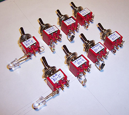
Diodes mounted on switches
The ScreamerLab clipping section contains the following diodes, connected to switches that allow each to be put in or out of circuit:
- 1N914 (2)
- 1N4001 Silicon Power diode
- 1N34A Germanium diode
- Yellow LED
Here are some possible settings:
- For stock TS808 clipping, switch one 1N914 on for each bus. All others should be off.
- For mild asymmetrical clipping, trying the stock setting on one bus, and on the other bus, turn on one 1N914s and the 1N4001.
- For hotter asymmetrical clipping use the stock setting on the first bus, and on the second bus, turn on both 1N914 and possibly the 1N4001.
The BYOC board contains three places for diodes. One is jumpered (Di1 on the Diagram). The ScreamerLab move the clipping diodes off-board to a collection of DPDT switches, as per the wiring diagram.
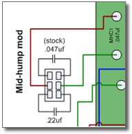
Mid-Hump Tone Mod
One of the sonic characteristics of the Tube Screamer is the pronounced mid-hump. This gives it a somewhat nasal tone--some folks love it, some hate it, others just consider it to be part of the Screamer Sound. The idea of the original design was most likely to roll off the bass to keep it from getting flubby/farty in the clipping stage.
To accomplish this, the stock TS-808 tone stack uses a .047uf cap which creates a high-pass filter (i.e. it passes higher frequencies through, and prevents low frequencies from going through) with a corner frequency of 720 Hz. This setting basically removes a lot of bass, most noticeably on the bottom two strings of the guitar.
To slightly flatten out the mid-hump and add a little bit of increased bass response, the .047uf part should be switchable. To accomplish this, do not solder the .047uf capacitor to the board. Instead move it off-board to a DPDT switch with a .22uf cap on the other side of the switch as per the ScreamerLab wiring diagram.
There are many other options here for the .22uf value. The value of the capacitor determines the frequency response of the tone stack. For a complete discussion of this part of the circuit, the ultimate resource is Jack Orman's Fat Bass for Tube Screamers article, available at: http://www.muzique.com/lab/fatt.htm. This article will help you understand the forces at work here. The ScreamerLab design for the mid-hump mod was based extensively on Jack's work, visit his site, he's the man. According to Jack, other values you can try instead of the hard-wired .22uf capacitor are shown here along with the frequency response are shown here:
|
Capacitor Value |
Corner Frequency (Hz) |
| .047uf | 720 |
| 0.1uF | 339 Hz |
| 0.22uF | 154 Hz |
| 0.47uF | 72 Hz |
| 1.0uF | 34 Hz |
You can see from this chart that we start at the stock .047uf capacitor with a corner frequency of 720 Hz, the standard TubeScreamer tone. From there, we work our way up in values all the way to 1.0uf which basically allows the tone-stack to cover the entire frequency range of a typical guitar pickup.
Distortion Boost Mod
The maximum setting on the Tube Screamer gain control is limited by the circuit's 4.7k Ω resistor. The Distortion Boost Mode provides more distortion by lowering that resistor value. The ScreamerLab design provides a DPDT switch that allows you to choose between the stock 4.7 value, or a 5k linear potentiometer. By lowering the value of the potentiometer, you increase gain. Note changing the value of the default 4.7 Ω resistor directly affects the tone stack also. In general, you want to balance the reduction in resistance with an increase in capacitance (as described in the Mid-Hump Mod) section.
Additionally, adding a boost in distortion comes with a price: increased noise. That is why I have added the LM833 part as one of the options in the opamp stage--its low noise characteristics can somewhat mitigate the increased noise.
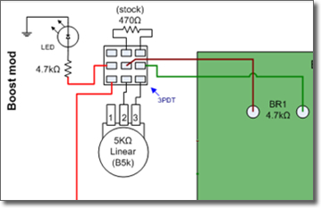
Do not install the 4.7kΩ resistor on the board. The Distortion Boost Mod is implemented with a 3PDT stomp switch which includes the stock 4.7kΩ resistor connected to one side of the switch and the 5k potentiometer on the other side. I've used a 3PDT stomp switch because this adds the ability to engage boost mode with your foot, and also adds a LED status indicator to see whether or not boost is engaged.
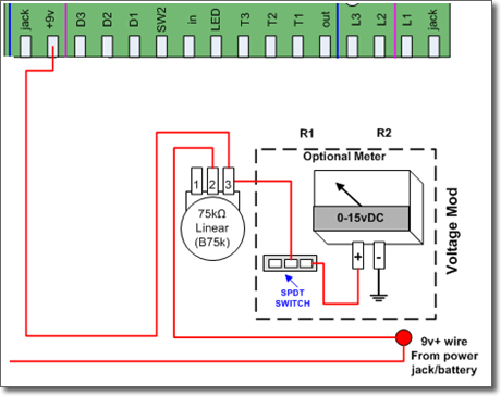
Voltage Mod
The components used in the TS series of pedals can typically handle up to 12 volts DC without problem. Increasing the voltage offers a bit more clean headroom. On the other hand sagging the voltage below 9 volts should have some interesting effects on the clipping section. The ScreamerLab has a 75k pot in series with the power supply so voltage can be left at the max of whatever is powering it (~9.6 v for a battery, up to 12v for an AC adaptor) or sagged lower for different sounds. I've included an analog voltage panel meter on the front so it easy to see where you are.
The Enclosure
To fit all the switches, knobs and various other parts, it was quickly apparent that the standard stompbox sizes wouldn't work. As with the FuzzLab, I used an LMB Heeger enclosure to give me enough space for all the stuff.
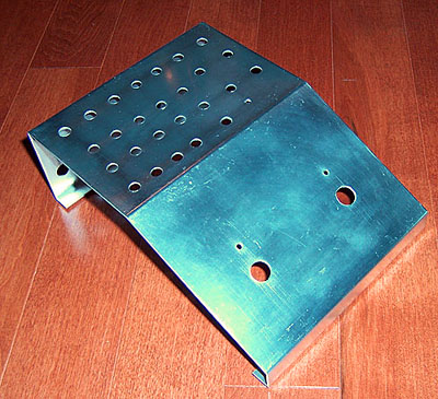
Enclosure drilled and ready to go
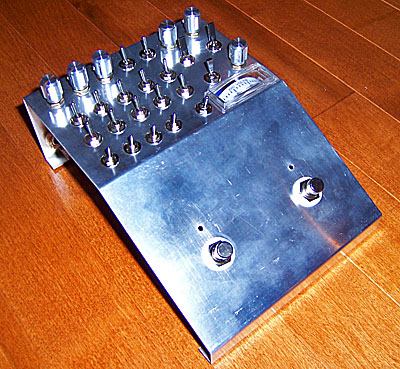
External parts added
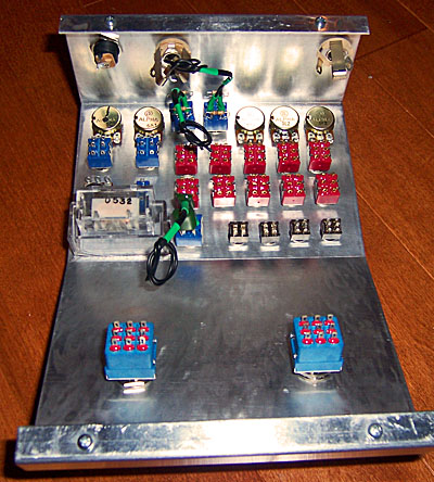
A peek inside
Current Status
Update 7 August 2006! This poor project keeps getting left forlornly on the shelf as my ADD compels me to try out other projects. So I decided to at least make a little progress and report my findings.
At this point, everything except the op-amp switching is working.
Observations:
- Clipping section - does all the standard symmetrical/asymmetrical stuff. Being able to switch different parts in and out on each side yields some interesting tones. Switch them all out of the chain and the pedal becomes a clean boost.
- Tone-Stack Mod- this changes the cap in the tone stack. I can go from the standard TS mid-hump tone to a full-through tone. Changes the pedal pretty dramatically.
- TS-808/9 Mod - This is switching the two resistors that appear in the output buffer between the 808 and 9. No audible difference. Useless mod.
- Cleanup Mod - Just sort of mucks with the gain in a different way. Haven't played with it enough to make a final decision yet....
- More Distortion - This is the part of the circuit that I added an additional stompswitch to. It does a pretty good job of making some pretty gritty distortion sounds.
- Voltage sag - not particularly useful unless you are running 12 volts into the box for more headroom. Sag allows you take it down to the standard ~9volts if you want the standard TS tone.
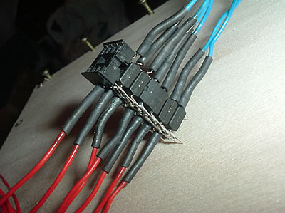
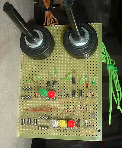
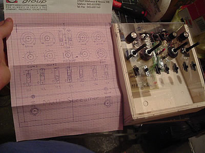
The Marco Version
I received a nice email from Marco in Verona, Italy. He is building his own version of the ScreamerLab and it looks like a very nice piece of work. Here are some photos Marco shared:

This work is licensed under a Creative Commons Attribution-NonCommercial-ShareAlike 4.0 International License.